On this page:
Atmospheric Cherenkov telescopes for high-energy γ-ray astronomy
Adapted from the article by J. Holder (Bartol), in the Particle Data Group Review of Particle Properties (C. Amsler et al., PL B667, 1 (2008) and 2009 partial update for the 2010 edition (available at http://pdg.lbl.gov ))
A wide variety of astrophysical objects are now known to produce high-energy γ-ray photons. Leptonic or hadronic particle populations, accelerated to relativistic energies in the source, produce γ rays typically through inverse Compton boosting of ambient photons, or through the decay of neutral pions produced in hadronic interactions. At energies below ∼ 30 GeV, γ-ray emission can be detected directly using satellite or balloon-borne instrumentation, with an effective area approximately equal to the size of the detector (< 1 m2). At higher energies, a technique with much larger effective collection area is required to measure astrophysical γ-ray fluxes, which decrease rapidly with increasing energy. Atmospheric Cherenkov detectors achieve effective collection areas of ∼ 105 m2 by employing the Earth’s atmosphere as an intrinsic part of the detection technique.
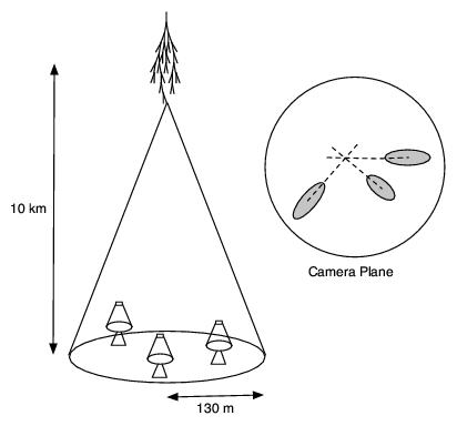
 A hadronic cosmic ray or high energy γ-ray incident on the Earth’s atmosphere triggers a particle cascade, or air shower. Relativistic charged particles in the cascade produce Cherenkov radiation, which is emitted along the shower direction, resulting in a light pool on the ground with a radius of ∼ 130 m. Cherenkov light is produced throughout the cascade development, with the maximum emission occurring when the number of particles in the cascade is largest, at an altitude of ∼ 10 km for primary energies of 100 GeV–1 TeV. Following absorption and scattering in the atmosphere, the Cherenkov light at ground level peaks at a wavelength, λ ≈ 300–350 nm. The photon density is typically ∼ 100 photons/m2 at 1 TeV, arriving in a brief flash of a few nanoseconds duration. This Cherenkov pulse can be detected from any point within the light pool radius by using large reflecting surfaces to focus the Cherenkov light on to fast photon detectors (see figure).
Modern atmospheric Cherenkov telescopes, such as those built and operated by the H.E.S.S. [1], MAGIC [2] and VERITAS [3] collaborations, consist of large (> 100m2) segmented mirrors on steerable altitude-azimuth mounts. A camera, made from an array of up to 1000 photomultiplier tubes (PMTs) covering a field-of-view of up to 5.0o in diameter, is placed at the mirror focus and used to record a Cherenkov image of each air shower. Images are recorded at a rate of a few hundred Hz, the vast majority of which are due to showers with hadronic cosmic-ray primaries. The shape and orientation of the Cherenkov images are used to discriminate γ-ray photon events from this cosmic-ray background, and to reconstruct the photon energy and arrival direction. γ-ray images result from purely electromagnetic cascades and appear as narrow, elongated ellipses in the camera plane. The long axis of the ellipse corresponds to the vertical extension of the air shower, and points back towards the source position in the field-of-view. If multiple telescopes are used to view the same shower (“stereoscopy”), the source position is simply the intersection point of the various image axes. Cosmic-ray primaries produce secondaries with large transverse momenta, which initiate sub-showers. Their images are consequently wider and less regular than those with γ-ray primaries and, since the original charged particle has been deflected by galactic magnetic fields before reaching the Earth, the images have no preferred orientation.
The measurable differences in Cherenkov image orientation and morphology provide the background discrimination which makes ground-based γ-ray astronomy possible. For point-like sources, such as distant Active Galactic Nuclei (AGNs), modern instruments can reject up to 99.999% of the triggered cosmic-ray events, while retaining up to 50% of the γ-ray population. In the case of spatially extended sources, such as Galactic supernova remnants (SNR), the background rejection is less efficient, but the technique can be used to produce γ-ray maps of the emission from the source. The angular resolution depends upon the energy of the primary γ-ray, but is typically 0.1o per event (68% containment radius) at energies above a few hundred GeV.
The total Cherenkov yield from the air shower is proportional to the energy of the primary particle. The image intensity, combined with the reconstructed distance of the shower core from each telescope, can therefore be used to estimate the primary energy. The energy resolution of this technique, also energy-dependent, is typically 15–20% at energies above a few hundred GeV. Energy spectra of γ-ray sources can be measured over a wide range; potentially from ∼ 50 GeV to ∼ 100 TeV, depending upon the instrument characteristics, source strength, and exposure time. To a first approximation, the lower energy threshold at the trigger level, ET , depends upon the mirror area, A, the photon collection efficiency, η(λ), the Cherenkov light yield, C(λ), the night sky background light, B(λ), the solid angle, Ω, and the trigger resolving time, τ , as follows [4]:

In practice, this function may be modified by the elevation angle at which the observations are made, and by the properties of the detector; for example, by complex, multi-level, combinatorial trigger systems and highly pixellated fields of view. In addition, the useful scientific threshold, after the application of analysis cuts to select γ-ray events, is always somewhat higher than this.
The first astrophysical source to be convincingly detected using the imaging atmospheric Cherenkov technique was the Crab Nebula [5], with a flux of 2.1 × 10⁻¹¹ photons cm−2 s−1 above 1 TeV [6]. Modern arrays have sensitivity sufficient to detect sources with 1% of the Crab Nebula flux in a few tens of hours, and the TeV source catalog now consists of more than 80 sources. The majority of these have been detected by scanning the Galactic plane from the southern hemisphere with the H.E.S.S. telescope array [7].
[1] J.A. Hinton, New Astron. Rev. 48, 331 (2004).
[2] J. Albert et al., Astrophys. J. 674, 1037 (2008).
[3] J. Holder et al., Proc. 4th International Meeting on High Energy Gamma-Ray Astron., eds. F.A. Aharonian, W. Hofmann & F. Rieger, AIP Conf. Proc. 1085, 657 (2008).
[4] T.C. Weekes, "The Atmospheric Cherenkov Imaging Technique for Very High Energy Gamma-ray Astronomy", arXiv:astro-ph/0508253 ; Lectures given at the International Heraeus Summer School, “Physics with Cosmic Accelerators,” Bad Honnef, Germany, July 5–16 (2004).
[5] T.C. Weekes et al., Astrophys. J. 342, 379 (1989).
[6] A.M. Hillas et al., Astrophys. J. 503, 744 (1998).
[7] F.A. Aharonian, et al., Astrophys. J. 636, 777 (2006).
Technologies used in the VERITAS Telescopes
Telescope Mechanics and Tracking
The basic mechanical structure of each VERITAS telescope is similar to that of the Whipple 10 m telescope. Each telescope consists of an altitude-over-azimuth commercial positioner (from RPM-PSI, Inc.) and a tubular steel Optical Support Structure (OSS). The camera is supported on a quadrapod, with a mechanical bypass of the upper quadrapod arm transferring the camera load directly to counter-weight supports located at the rear of the OSS. The positioner is a commercially manufactured unit, while the OSS custom-designed.
The maximum slew speed of the telescopes is 1 degree per second with the positioner encoder measurements being logged to an offline database at a rate of 4 Hz. These values are used to monitor any pointing discrepancies with the telescopes. The mechanical pointing accuracy of a VERITAS telescope is typically better than ± 0.01 degrees [1].
Telescope optics
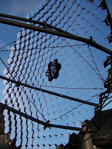
The optics of each VERITAS telescope follows the Davies-Cotton design [2] using 350 identical hexagonal spherical mirrors (of area 0.322 m2 and radius-of-curvature of approximately 24m) giving a total reflector area of 110 m2. The use of hexagonal facets allows the full area of the OSS to be exploited.
Each mirror facet is made from glass, slumped, polished and then aluminized and anodized. The exposure of the mirror facets to the Arizona desert and the elements will cause the mirror reflectivity of the telescopes to degrade (approximately 3 - 6% of reflectivity at 320nm is lost per telescope per year). To counter the effects of this weathering on the mirror reflectivity, a regular program of re-aluminization and re-anodization of VERITAS facets is carried out at the VERITAS optical coating laboratory (located at the Fred Lawrence Whipple Observatory) and the mirrors are regularly washed. Aluminizing is the process of evaporating aluminum onto a glass surface to create a mirror. The evaporation must be done under vacuum to ensure the purity of the coating which is important for the optical properties and for strong adhesion. Anodizing is the process in which the top layer of the aluminum coating is converted into a harder and more durable layer of aluminum oxide. This is accomplished by submerging a freshly aluminized mirror in an electrolyte solution (ammonium hydroxide, tartaric acid, distilled water and ethylene glycol) which then has an electrical current passed through it. The thickness of the anodized layer determines the wavelength at which peak reflectivity of the mirror is obtained. For VERITAS mirrors, approximately 80nm of the aluminum coating is oxidized which ensures that the reflectance of the mirrors exceeds 90% at 320nm (in the wavelength regime of Cherenkov radiation). Each mirror facet also focuses >90% of light onto a circle of diameter 5.7 ± 1.9 mm [3] which is well within the diameter of a VERITAS PMT (see Cameras section below). Each mirror is mounted on the OSS via a triangular frame with 3 adjustment screws (these adjustment screws are used in alignment of the optics, see discussion below). More details of the work carried out at the VERITAS mirror maintenance lab at the Fred Lawrence Whipple Observatory can be found in [4].
The use of multiple mirror facets offers several advantages over one single dish. The cost of a single 12 meter aperture mirror would be excessive for the purposes of the IAC technique. In addition, its weight would complicate the design and implementation of the OSS and positioning systems for the telescopes. The Davies-Cotton design is simple to implement, with mirror replacement and mirror re-coating undertaken locally as previously mentioned.
The individual mirror facets need to be manually aligned so that the entire reflector will act as a single dish with a closely distributed Point Spread Function (PSF). The PSF describes the response of an imaging system to a point source of light at infinity. The smaller the value for the PSF, the better aligned the optical system is (i.e. more focused).
The current methodology for mirror alignment uses the "raster" scan method [5]. This method employs a CCD camera, placed at the focal point of the reflector, which takes a series of images of the reflector while the telescope performs a scan (in a rectangular pattern) about a star. Properly aligned mirror facets appear bright when the telescope is pointing directly at a star, while misaligned facets will appear bright when the angle between the star and the facet is twice the misalignment angle of the mirror. Therefore, by analyzing the series of images from the scan one can determine which mirrors are misaligned and the angle of misalignment. These mirrors can then be readjusted (using the adjustment screws mentioned above) to correct their position on the dish.
Cameras
The camera in a VERITAS telescope is located at the focal plane of the telescope (12 meters from the mirrors) in a ``focus box" of dimension 1.8m x 1.8m. This focus box is light and water tight and uses a rolling-shutter system which is located at its front, allowing light to reach the camera when opened and providing protection from sunlight and the weather elements when closed. The camera consists of 499 closed-packed circular photomultiplier tubes (PMTs, see below), giving an angular pixel spacing of 0.15 degree and a total field-of-view (FOV) of 3.5 degrees.
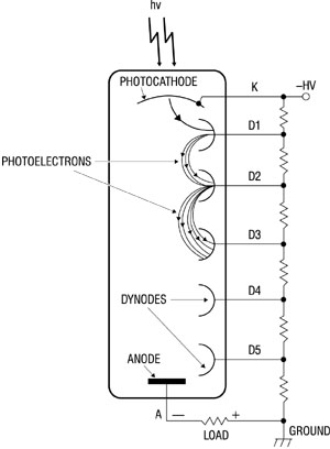
A photomultiplier tube is an extremely sensitive light detector (mainly sensitive to ultraviolet, visible and near-infrared wavelengths) that is commonly used in many fields such as nuclear and particle physics, astronomy, and medical imaging and diagnostics. It consists of a photo-cathode (an electrical conductor that releases electrons from its surface when illuminated) which is contained in a shell with an internal vacuum. When a photon strikes the photo-cathode, electrons (known as "photoelectrons") are liberated and directed via an electric field to strike an electrode (called a dynode) within the PMT shell. Several secondary electrons are produced for each impacting photo-electron. These secondary electrons are in turn directed to a second dynode creating more secondary electrons which are directed to the next dynode and so on. This process creates a huge gain of electrons at the end of the dynode chain (up to 1,000,000 electrons can be generated for a single initial photo-electron, for example). The electrons are collected by an anode which provides the signal current to be read out [6].
The use of photomultiplier tubes in ground based gamma-ray astronomy is motivated by their relative low-cost, fast response times, large detection areas and sensitivity in the UV/Blue region of the electromagnetic spectrum (the relevant spectral emission region for Cherenkov radiation); they also provide large signal-to-gain for the detection of incident Cherenkov light. The PMTs used in the VERITAS cameras are 29mm diameter Photonis XP2970/02 tubes with 10 gain stages. This model of PMT is most sensitive in the UV band and has a fast rise-time (1.9ns), necessary to resolve the nano-second Cherenkov flashes (~4-6ns) . This model has a typical quantum efficiency (defined as the percentage of photons hitting the PMT photo-cathode that create a photo-electron) of ~20% at 320 nm. The PMTs in VERITAS are generally operated with a gain of approximately 2 x 10⁵ (i.e. for every electron produced at the photo-cathode of the PMT, around 200000 electrons are collected at the anode). The high voltage (HV) supply for the PMTs is provided by a multichannel modular commercial power supply (by Caen Spa), allowing the HV of each PMT to be controlled individually.
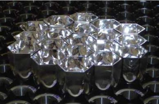
 Each VERITAS camera's 499 circular PMTs are arranged in a hexagonal pattern which maximizes the light collection efficiency of the camera. However, resultant gaps between pixels remain, through which light is lost. To remove this dead-space a light-concentrator plate consisting of 499 individually molded plastic ``light cones" on a machined heavy plastic plate [7] is attached to the front of the VERITAS cameras. The light cones used with VERITAS are a hybrid of the Winston light concentrator design [8] which maximizes the collection of incoming rays over the desired field-of-view while also helping to reduce background light incident on the photosensitive area of the PMT (albedo protection).
The Trigger System
At the low end of the VERITAS energy range, fluctuations in the night sky background (NSB) and single muons from cosmic-ray showers constitute a large unwanted background signal. VERITAS employs a three-tier trigger system to reduce the rate of these background events. The first trigger system works on the single-pixel level, the second checks for specific patterns of single level pixels within a timing window, and the third works at the array level, requiring simultaneous observations of an air-shower event in multiple telescopes (ensuring a "stereoscopic" view of the event). The three trigger levels are designated L1, L2 and L3.
Level 1
The L1 trigger system consists of custom-built Constant Fraction Discriminators (CFDs) and threshold discriminators [9], one for each PMT in a telescope camera. The output from a PMT is directed into the CFD which produces an output logic pulse if the sum of the voltages from the PMT pulse and a time delayed copy crosses a pre-defined threshold. Currently, the VERITAS CFDs are operated with a 50 mV threshold (corresponding to approximately 4-5 photo-electrons).
Level 2
For Cherenkov telescopes, the single pixel trigger rate can be highly susceptible to NSB fluctuations (especially for low trigger thresholds) and to PMT after-pulsing. These fluctuations would generally affect one or two adjacent pixels at a time. Therefore, to successfully reject these fluctuations and allow a lower trigger threshold of the CFDs, a second-tier trigger is employed. This Level 2 (L2) trigger is based on topological rejection of pixel triggers by only triggering an output pulse when several adjacent pixels surpass the L1 discriminator threshold within some coincidence window (about 6 ns).
Level 3
A large source of background for Cherenkov telescopes at low energy is due to local muons. These muons will be relativistic and thus generate Cherenkov radiation. When generated close to the telescope (i.e. locally) but with an origin a large distance from the camera center, they can create images in the camera that are nearly identical to those from gamma rays. However, the Cherenkov cone from a local muon will only be large enough for detection by a single telescope. Therefore, an array-level trigger which depends only on receiving telescope level triggers from more than one telescope will effectively remove the muon background. The removal of the largest fraction of single telescope triggers (i.e. local muons) allows the CFD thresholds to be lowered (into the regime previously dominated by muons), further increasing the sensitivity of the detector to low energy gamma rays. More details on the VERITAS trigger system can be found in [10].
Data Acquisition
The digitization and buffering of the PMT signals is performed using custom-built 500 MSample/sec (2 ns sampling) flash-ADC boards [11]. The signal from each PMT in the camera is transferred via coaxial cable to an individual channel on the front-end of an FADC board (a single VERITAS FADC board contains 10 channels). The signal is then digitized at a sample rate of 500 MHz (i.e. one sample every 2 ns) with each FADC providing an 8-bit dynamic range and buffer depth of 64 microseconds. When the Level 3 trigger system identifies an air-shower event, it sends a logical signal to each telescope, directing the telescope data acquisition system to read out a section of this buffer (48 ns worth or 24 samples) for each PMT signal. The high-resolution digitization of the PMT signals provided by the FADC boards preserves the shape and timing information for later offline application of signal processing techniques. Information on the pulse rise-time and relative arrival time can then be used to minimize the charge integration window per pixel, thus giving an improved signal-to-noise ratio.
The digitized signals from the FADC boards are buffered and read out to a telescope level event-building computer, where complete events are integrated, tested and passed to a data harvester machine. The harvester machine works on the array level, combining the telescope level event information with array level information into a custom VERITAS data format for later offline analysis.
Environmental Monitoring
For the detection of Cherenkov pulses from incident gamma-ray-induced air showers, it is of great importance that the weather be of a high standard (i.e clear dry nights). Any observations taken during poor weather will be negatively affected by the presence of clouds in the VERITAS field of view and will need to be rejected from any analysis. To quantify the "quality" of the night's sky on any given night the temperature of the sky is monitored using 3 infrared pyrometers. The pyrometers measure the radiant temperature of the sky in the mid-infrared spectrum (8 - 14 micrometers). The atmosphere in this spectral range does not radiate IR, but water vapor and droplets will act as IR emitters and can be detected as a corresponding temperature rise in the pyrometer. Therefore, a rise in sky temperature in the FOV of the pyrometers indicates the presence of water vapor (i.e. clouds or haze). Two of the devices (one with a spectral sensitivity range of 8 - 14 micrometers, the second with a range of 9.6 - 11.5 micrometers) are placed on the OSS of two VERITAS telescopes, while the third is placed with a fixed viewing angle on the L3 electronics building (this third pyrometer has a 6 degree FOV). The pyrometers are queried for a reading every 10 seconds and these values are logged to the VERITAS offline database and also plotted via live-time array monitor software.
The array monitor software displays measurements from a weather station positioned on the roof of the central L3 electronics trailer to observers during the night. This station is equipped with a wind speed/direction sensor, humidity sensor, rainfall and temperature sensor. These measurements are logged to the offline database along with the relevant time-stamps. VERITAS does not operate if the wind is gusting above 50 kph or if humidity levels reach greater than 50% (to protect the telescope mechanics and sensitive electronics systems).
A CCD camera is located on one of the quadropod arms of each VERITAS telescope for use as an optical monitor of the telescope pointing (with arcsecond precision) and the night sky conditions in the FOV. Images are updated every 2 seconds.
[1] J. Holder et al. "The first VERITAS telescope". Astroparticle Physics, 25: 391-401 (2006). doi: 10.1016/j.astropartphys.2006.04.002 , astro-ph/0604119.
[2] J. M. Davies and E. Cotton. Journal of Solar Energy, 1957.
[3] K. Gibbs et al. "The VERITAS Atmospheric Cerenkov Telescopes: Positioner, Optics and Associated Components". Volume 5 of the Proceedings of the 29th International Cosmic Ray Conference (Pune, India), pages 2823-2826, July 2003.
[4] E. Roache et al. "Mirror Facets for the VERITAS Telescopes". Volume 3 of the Proceedings of the 29th International Cosmic Ray Conference (Pune, India), pages 1397-1400, 2008.
[5] A. McCann et al. "An new mirror alignment system for the VERITAS telescopes". Astroparticle Physics, 32: 325-329 (2010). doi: 10.106/j.astropartphys.2009.10.001.
[6] "The Photomultiplier Handbook". Available from psec.uchicago.edu/links/Photomultiplier_Handbook.pdf .
[7] T. Nagai et al. "Focal Plane Instrumentation of VERITAS", Proceedings of the 30th International Conference on Cosmic Rays, Merida, Mexico, 2007. NASA ADS copy.
[8] R. Winston. "Light collection within the framework of geometrical optics". J. Opt. Soc. Am., 60(2): 245-247, 1970.
[9] V.V Vassiliev. "Veritas CFDs". In Proceedings of the 27th International Cosmic Ray Conference, Volume 5, page 2851, July 2003.
[10] A. Weinstein. "The VERITAS Trigger System". In Proceedings of the 30th International Cosmic Ray Conference, Merida, Mexico, volume 3, pages 1539-1542, 2008.
[11] P. F. Rebillot et al. "The VERITAS Flash ADC Electronics System". Proceedings of the 28th International Cosmic Ray Conference, Tsukuba, Japan, volume 5, pages 2827, July 2003.

